Ask An Expert
Frequently Asked Questions
Yes, We can supply simple stand alone panels or automated PLC controlled systems. We normally install and test all controls on our mixers before they are shipped.
Yes, we normally test the mixers before they are shipped and mark out the wire need to connect on the control box.
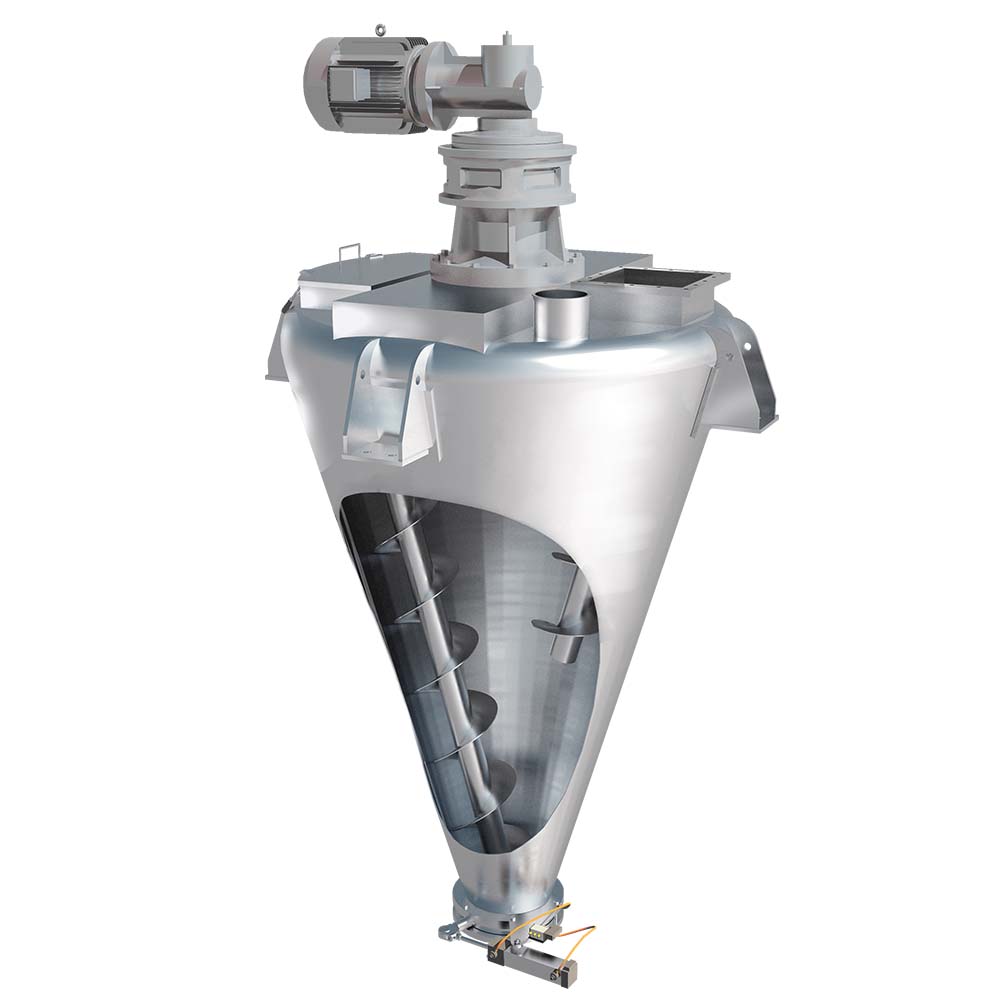
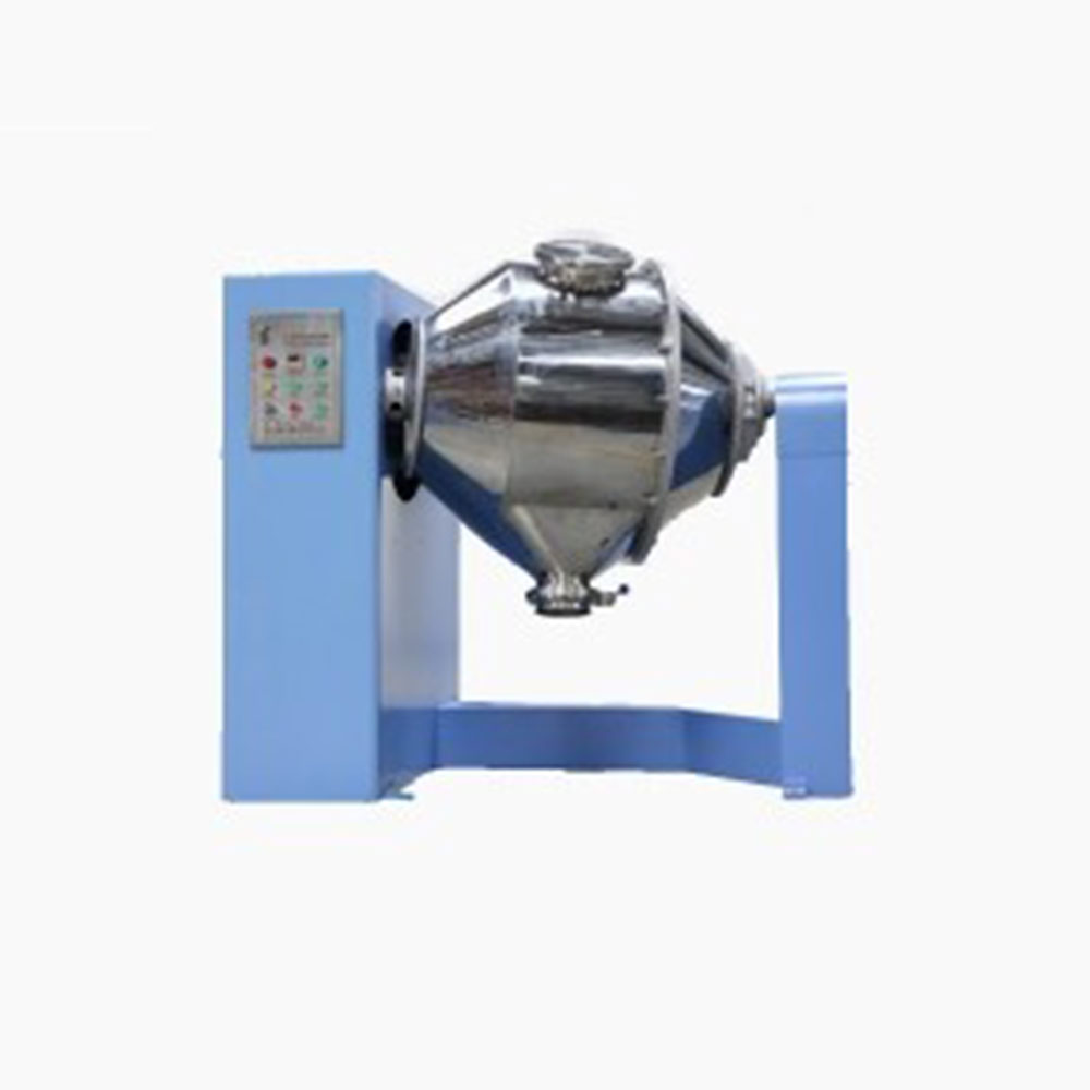
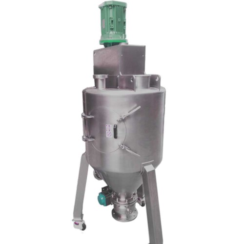
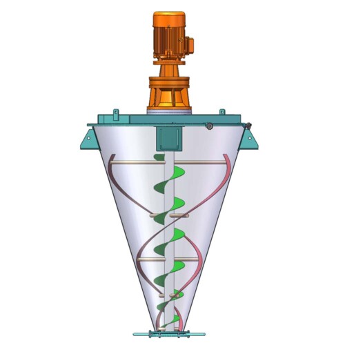
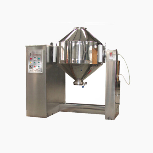
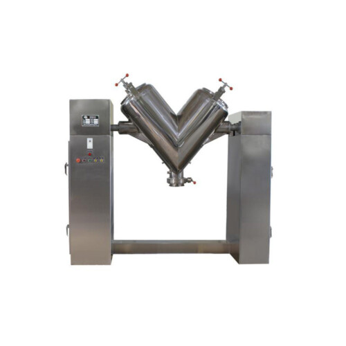
We manufacture specialty mixing equipment for powder & bulk materials. Included are ribbon blender, plough mixer, conical screw mixer, twin shaft paddle mixer, V blender, double cone blender and other auxiliary equipment such as screw conveyor, quantitive auger filler.
We sell across the world, our cusotmers distribute 5 continents.
Share Us With Your Network


Single shaft batch ribbon blender selection guide
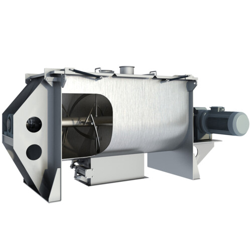
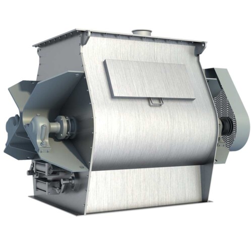
Because it can mix almost any bulk solids together, the ribbon blender is considered the workhorse of solids-solids mixing. The unit can also mix small amounts of liquids into a solid. The ribbon blender can operate continuously or in batches and with one or two mixer shafts. This article introduces you to the single-shaft batch ribbon blender. After explaining how the mixer works and describing ribbon assembly variables, construction materials, and equipment configurations, the author provides information on how to select and maintain the mixer. Related information specifies what you need to tell the mixer manufacturer about your mixing needs during the selection process.
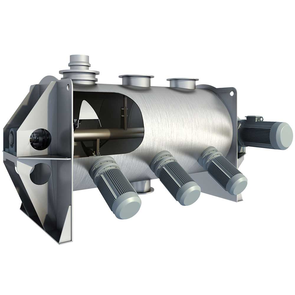
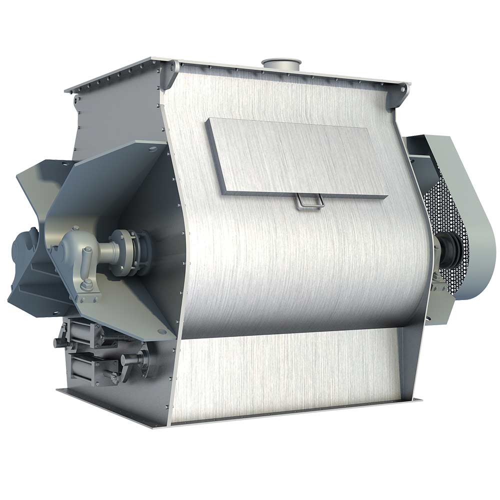
A single-shaft batch ribbon blender is shown in Figure 1. The unit consists of a horizontal, U shaped vessel, called a tub or trough, that is equipped with a rotating shaft powered by a drive. The shaft, which is mounted at the tub’s end plates, is fitted with metal spokes and inner and outer helical blades called ribbons; together, the shaft and attachments form the ribbon assembly, show in Figure 2. (In some units, the shaft has paddles or plows.) The clearance between the outer ribbon tips and the tub is typically 1/8 to 3/16 inch, depending on the manufacturer.

Figure 1

Figure 2
As or after the materials are loaded into the mixer, the shaft rotates, this causes the outer ribbon to move the materials toward one end of the mixer while rotating the materials around the shaft. The inner ribbon produces an equal and opposite force that pushed materials to the mixer’s other end while rotating materials around the shaft in the opposite direction. This produces a constant end-to-end, side-to-side mixing action as the ribbons move through the particles, dividing, separating, and redistributing them behind the ribbons.
Typically, particles must move from one end of the mixer to the other several times before the materials are homogeneously mixed. For most materials, this process takes about 2 minutes. Finally, the mixture is discharged. (for faster and more thorough mixing, a twin-shaft ribbon blender is an option, the mixer typically has twin tubs with a ribbon assembly in each and achieves intensive mixing by agitating material between the shafts in addition).
To achieve high-quality mixing with a single-shat batch ribbon blender, you need to choose the right unit for your process and then maintain it properly. The first step is learning what batch ribbon blender options are available and how they affect the mixing operation.
Ribbon assembly variables
Choosing the ribbon assembly that’s right for your application can improve your mixing speed and mixture quality. Combined with the mixer length-to-width ratio, three factors—the ribbon assembly speed, the ribbon pitch, and the ribbon width and spacing – – must be in balance for satisfactory mixing. The shorter the mixing time, the more critical this balance becomes.
Length-to-width ratio. The mixer typically has a length-to-width ratio of 2:1. This short and wide shape helps material move quickly up and down the mixer’s length. A longer mixer provides slower mixing, which may be acceptable if your mixing time isn’t critical of if your plant layout doesn’t allow the shorter, wider configuration.
Ribbon assembly speed. The ribbon assembly speed typically doesn’t refer to shaft’s revolutions per minute, but instead to the ribbon tip’s speed (in feed per minute), because most mixing action occurs at the ribbon tips. While the mixer manufacturer’s speed range information is typically proprietary, the manufacturer can recommend a speed suited to your material and mixing goals. Of all the factors, the ribbon assembly’s speed is the easiest to vary after the mixer is installed.
Ribbon pitch. The ribbon pitch, which is the distance between the spokes supporting the ribbons, generally ranges from about 0.75 or 0.8 to 1.5. The mixer manufacturer typically installs the ribbons at a standard pitch.
Ribbon width and spacing. The inner ribbon is wider than the outer ribbon because the inner ribbon moves at a slower speed and requires more surface area to push the material. Thus, the closer the spacing between the inner and outer ribbons, the less width the inner ribbon requires and the lower the ribbon’s cost. To achieve quicker mixing, you can increase the ribbon width, but this will also increase the mixer’s horse power requirements and operating cost.
Construction materials
The batch ribbon blender can be constructed of various materials and with various interior coatings and liners. For non-sanitary applications, the mixer is typically constructed of carbon steel. Non-sanitary construction leaves small cracks and crevices in the joints between the mixer’s metal plates (for instance, between the tub and an end plate), which can accumulate material. This construction is suitable only for mixing a noncorrosive material and for an application that doesn’t require frequent washdowns between batches.
For mixing a corrosive material or a food product, or for an application that requires frequent mixer washdowns, the mixer is usually made of stainless steel. However, the joints can still have small cracks and crevices, which can be acceptable if small amounts of material carryover from batch to batch don’t affect your mixture’s end quality. But to meet stricter purity requirements, specify a stainless steel interior finish(for instance, with welded and ground metal joints) and whether the mixer’s construction must meet 3-A sanitary standards or USDA, FDA, or other approval. Rely on the mixer manufacturer’s advice in choosing a stainless steel finish to ensure you don’t specify a higher grade finish than you need, which can save money.
The mixer’s interior can also be coated with polyurethane or lined with replaceable steel for handling abrasive materials. In some cases, an epoxy coating can be wprayed on the ribbon assembly and inside the tub to reduce the buildup of sticky or wet materials.
Equipment configurations
The batch ribbon blender’s configuration – including the drive, seal, cover, discharge, liquid addition components, and the thermal jacketing – depends on your application requirements and preferences and the mixer manufacturer’s engineering requirements and constraints.
Drive. The mixer manufacturer will select a drive typically ranging from a few to 100 or more horsepower, depending on your batch volume and the material’s bulk density and other characteristics. For instance, mixing large volumes of salt or minerals with bulk densities of 60-80 lb/ft3, or starting the mixer under load, will require higher horsepower. The manufacturer’s standard drive or sheaves, sprockets, or gear reducers (or all three) can be used to reduce the motor’s output revolutions per minute to the mixer shaft’s required revolutions per minute.
Seal. The type of seal needed around the shaft at the mixer’s end plates depends on your application. The seal can range from a simple, inexpensive Babbitt seal for an application that doesn’t have to meet strict purity requirements to an air-purged packing gland that uses air to purge material buildup from the seal to prevent batch-to-batch contamination in a sanitary application. The mixer manufacturer typically selects the seal based on experience or on your request for a specific type.
Cover. Material is loaded into the mixer through a top opening with a cover that can be simple or complex. The standard cover is 10-gauge steel, but for a mixer under pressure, the cover can be ½ inch steel and include gasketing for a tight seal. The cover is typically constructed from the same materials and to the same standards as the mixer vessel. The best opening location is near the center of the mixer’s length to speed material movement inside the tub. The opening is typically fitted with a grate to prevent an operator from inserting a hand or falling into the mixer; a safety microswitch can be linked to the grate to stop the mixing operation if the grate is removed. You can also fit a spout inlet flange on the mixer opening to provide an air-tight connection to a weigh hopper above the mixer. You’ll need to carefully plan the size and location of the opening and cover along with those of the other components.
Discharge. The mixer discharge is installed at the mixer bottom and can be a single or multiple gate unit or a drop-bottom discharge. Like the cover, the discharge is made from the same materials and to the same standards as the vessel. Each unit’s discharge time depends on the mixer’s size and your material characteristics.
A slide gate (or butterfly valve for a sanitary application) is typically used for the single or multiple gate discharge, and either can open manually, pneumatically, or electrically for discharge. The single-gate unit usually discharges into a conveyor or bin. The unit doesn’t discharge as quickly as the multiple-gate or drop-bottom discharges, so it’s used when the mixer has a long batch cycle time and doesn’t need to discharge quickly. The single-gate discharge is also used when total cleanout between batches isn’t necessary, because the ribbon-to-tub clearance at the mixer bottom is relatively large and the area can collect material that won’t exit during discharge.
A faster batch cycle time requires a multiple-gate discharge or a drop-bottom discharge. The multiple-gate discharge consists of several slide gates or butterfly valves in the mixer bottom. They open simultaneously to discharge material into a surge bin, which holds the mixture while the next batch is being mixed. Although the units discharge rapidly, they don’t provide complete cleanout because, as with the single-gate discharge, some material can collect on the mixer bottom and between the discharges.
A drop-bottom discharge consists of one or two large doors that cover the entire mixer bottom. The discharge is typically operated pneumatically, electrically, or hydraulically. The discharge opens completely to instantaneously discharge material into a surge bin, making it ideal for an application requiring quick discharge. The discharge also completely empties materials that don’t adhere to the mixer surfaces.
Liquid addition components. Adding a liquid to the material in the mixer requires installing a spraybar, fitted with several nozzles, that runs along the mixer’s length. The liquid flows through the spraybar, sprays out the nozzles, and contacts the material. For best results, make sure the components meet these requirements:
• The liquid should be sprayed as fine droplets to avoid agglomerating the material. If necessary, you can add high-speed choppers to the mixer to disperse and mix large agglomerates produced by adding the liquid.
• The liquid should be introduced directly into the material, not onto the ribbons. Position the nozzles so that they spray the liquid up into the material rather than onto the ribbon assembly.
Thermal jacketing. If you need to heat or cool the mixer’s contents, you can install an external jacket consisting of metal coils filled with steam or cool water. A typical example is installing a cooling jacket for a heat sensitive pharmaceutical mixture. Coil location depends in part on the location of the mixer’s other components.